Introduction
This exercise will show you how to convert an AutoCAD DWG (*.dwg) file to MicroStation DGN (*.dgn) format. The AutoCAD roads data is divided into different layers for each road type, each of which has a different symbology. We\'ll use FME to convert this roads data to MicroStation, alter some of the symbology, write DWG attributes to Microstation tags, and merge a few of these layers together.
Downloads
- roads.zip
- acad2dgnv8-begin.fmwt{#15799}
- acad2dgnv8-complete.fmwt{#15800}
- seed2d-ft-v8.dgn{#15801}
Feel free to download and unzip the data (roads.zip file) attached to this exercise if you\'d like to perform these steps yourself as we go along!
Source Data
The data used in this exercise originates from open data made available by the City of Vancouver , British Columbia. It contains information licensed under the Open Government License - Vancouver.
Step-by-Step Instructions
To create the demo, you will need to carry out the following steps.
1) Start FME Workbench
In Windows this is found under Start > All Programs > FME Desktop > FME Workbench
2) Select Generate Workspace
This is found on the Create Workspace section of the FME Workbench interface. Alternatively, use Ctrl+G as a shortcut.
3) Browse to and select the source (reader) dataset
Browse for and select the source AutoCAD data (Roads.dwg). The file extension for Roads.dwg tells FME what format of data we are working with (Autodesk AutoCAD DWG/DXF).
4) Set the output (writer) format to Bentley Microstation Design (V8) DGN
Select Bentley Microstation Design (V8) DGN for the format for the writer; do this by typing the name into the field until it appears within the dropdown list.
5) Set the output dataset location
Set your output location to whatever best suits your directory structure. If you are using the template file above, it will write your output to a Roads folder in your template folder (on Windows, C:\Users\USERNAME\AppData\Local\Temp\, with template data stored in folders beginning with wb_template).
6) Modify the input parameters
Click the Parameters button for the reader. The Autodesk AutoCAD DWG/DXF Parameters dialog box opens.
- Select Group Entities By 'Attribute Schema'. This means we can visualize the layers of data with attribute information.
Notice how there are also parameters on this dialog box to control other aspects of reading DWG data.
7) Modify the writer parameters
Click the Parameters button for the writer. The Bentley MicroStation (V8) Parameters dialog box opens.
- First, we will change the seed file from being 3D to 2D. Using the box next to Seed File (V8 only), navigate to the new seed file (seed2d_ft_v8.dgn). You can download it above or find it in your FME installation folder under .\FME 2018\design\seed2d_ft_v8.dgn.
- Next, we will tell FME to write tags for the features. Use the drop-down list from Write Tags and select 'yes'. Click OK to dismiss the Bentley MicroStation (V8) Parameters dialog box. Click OK to create the workspace and OK again to include all feature types from the reader.
8) Modify feature schema ("Schema Mapping")
If we\'re happy with an exact copy of the source data we could just run this translation now, but we want to make some changes first.
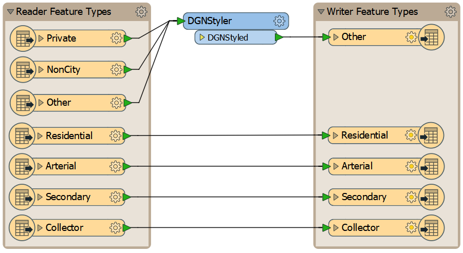
- First, merge the 'private', 'noncity' and 'other' layers into a single layer called 'other'; we can do that easily by dragging the connections onto the 'other' input port. We call this schema mapping.
- We no longer need the 'noncity' and 'private' writer feature types, so delete them.
9) Add the DGNStyler transformer
In addition, we can modify the output symbology by using a transformer in FME called the DGNStyler. Add a DGNStyler before the Other writer feature type by selecting its input port and typing DGNStyler to bring up the transformer in the Quick Add menu. Double-click it or press enter to add it to the canvas, which should now look like this:

DGNStyler on the canvas
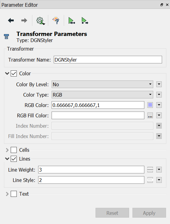
Click the DGNStyler to open it in the Parameter Editor window. Let's add some parameters to style the Other writer feature type:
- Expand and click the 'Color' checkbox. Set a lilac color for the output features under 'RGB Color' (e.g. 0.666667,0.666667,1).
- Expand and click the 'Lines' checkbox.
- Set the 'Line Weight' to 3.
- Set the 'Line Style' to 2.
Your DGNStyler Parameter Editor window should now look like this:

DGNStyler parameters
10) Click the Run button on the toolbar
Run the workspace by clicking on the green play button. This carries out the translation.
11) View the DGN file in a MicroStation Viewer
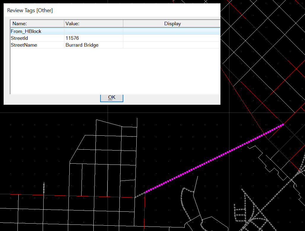
Once complete, use a file browser to locate the output dataset. If we use a 3rd party CAD viewer such as Bentley View to inspect the data, we will see that the line data in the DGN file has been written using the symbology specified in the DGNStyler, and DWG attributes have been written into Microstation tags. Here you can see the Burrard Bridge in Vancouver has been styled under the Other writer feature type (dashed line) and has its attributes as tags.

DGN tags in our translated data as seen in Bentley View.