Introduction
The goal of this exercise is to demonstrate how to work with exploded blocks in FME. Specifically, we will look at translating a DWG file into a PDF.
Downloads
Source Data
In the image below, we see a DWG file containing two blocks with text saved in a separate layer. In this example, we will only be looking at one block to serve as a simple case demonstrating how to write blocks to a PDF.
Next to the the wheel blocks are text labels indicating an ID for the wheel. This is not contained within the block, but rather it is stored on the BicycleParts layer.
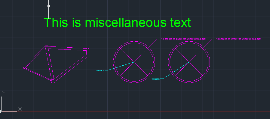
BlockTemplate.dwg
Step-by-Step Instructions
1) Open FME Workbench. Start with a blank workspace.
In Windows this is found under Start > All Programs > FME Desktop > FME Workbench. You can click New under the Start tab (or press Ctrl + N) and select Blank Workspace to create a new blank workspace.
2) Add AutoCAD DWG/DXF reader.
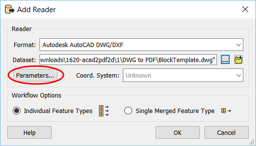
From the Readers menu, select Add Reader. Fill in the reader and dataset parameters, using BlockTemplate.dwg as your Dataset. Then, click the Parameters button:
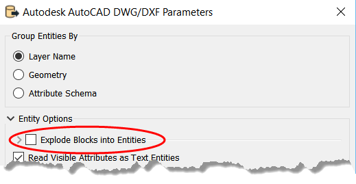
In the Parameters dialog, ensure that 'Group Entities By' is set to 'Layer Name' and the 'Explode Blocks into Entities' option is checked. This will explode the block into its constituent features (in this case, ellipses and polygons) so it will be displayed in the PDF just like it is in AutoCAD.
Click OK, then OK again.
3) Select Feature Types
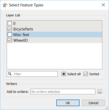
When prompted to select layers to read, you will only need to select the layer that contains the blocks and the layer that contains the text you are interested in. The layer containing the block we want is on a layer named 'BicycleParts', and the layer containing the text we want is named \'WheelID\'. Only check these layers to be added to the canvas.
4) Expose format attributes
Once the reader is added to the canvas, the next step is to extract the block we are interested in. To do this, we first need to expose two format attributes.
Click the BicycleParts reader feature type to open its properties in the Parameter Editor window. Click on the Format Attributes tab. Check autocad_block_name. Click Apply.
Next, open the properties of the WheelID reader feature type. Click on the Format Attributes tab. Check autocad_layer. Click Apply
5) Add Tester
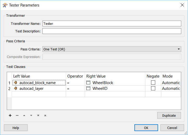
Add a Tester to extract only the block we want from BicycleParts, and also the text which is contained in a separate layer (WheelID). Connect both of the reader feature types to the tester.
We know that our block name is WheelBlock, after examining the data in AutoCAD or in the FME Data Inspector. Within the Tester transformer parameters, we want to test if the format attribute autocad_block_name = WheelBlock, or if autocad_layer = WheelID.
6) Add Writer
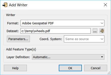
From the Writers menu, select Add Writer.
Add a writer to your canvas in the Adobe Geospatial PDF format (PDF2D). Name the output layer something meaningful. Change the Layer Definition to Automatic.
7) Run workspace
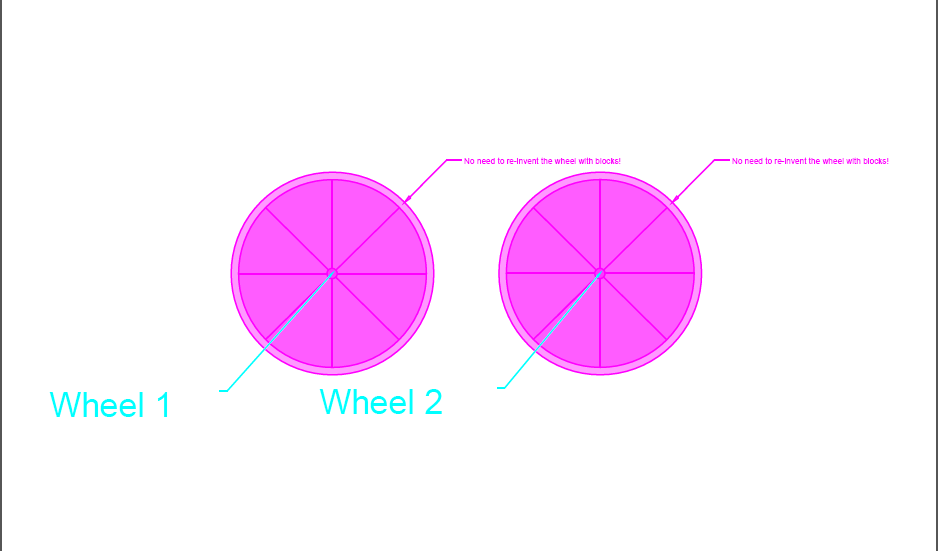
Run the workspace and check out the results. You will find a PDF in the output directory you chose in step 6 showing the block of interest:
Of course, you could use the DWGStyler transformer to modify the colour of the block as well! Additionally, new for 2018.0 betas: you can read the PDF into a workspace using the new PDF reader.