| CAD-GIS Data Integration Scenario | |
| Data | Water distribution network (Esri SHP) Road network (Esri SHP) Parcel polygons (Esri SHP) Electrical grid from [BC OneCall](https://www.bconecall.bc.) (Esri SHP) |
| Overall Goal | Use your FME skills to take GIS data and generate CAD site drawings for parcels requiring water pipe replacement. |
| Demonstrates | GIS-CAD translation, storing attributes as extended entity data |
| Start Workspace | None |
| End Workspace | None. Instructors can access final workspace here. |
Introduction
In the previous exercises you have learned how to translate GIS and CAD data using FME. Now let's put that knowledge to use! As we covered in the Lecture section, GIS-CAD data integration is an important, but complex process. In this exercise you will develop a workspace that solves a GIS-CAD data integration problem.
This exercise offers less guidance than the previous ones; you will have to explore FME for yourself in order to solve the problem. To get started, we will provide an example of one CAD-GIS translation from the scenario data. After that you can follow similar steps for the remaining datasets. If you have trouble carrying out the steps you can refer to the FME Workbench Help (also available online in our Documentation) or the community Knowledge Center.
Exercise Goals
We have several goals for the exercise:
- Identify water network pipes that are older than 1935 to schedule them for replacement
- Create CAD site drawings of each property parcel that will be affected by this replacement
- Create an Excel file for the department who will conduct mass-mailings to alert affected property owners
- Add existing CAD data to the department's Esri Geodatabase, including validation
We will start with our data in the common GIS format Esri shapefile format and translate it to AutoDesk .dwg and Excel .xlsx formats. Along the way we will use several transformers to alter the structure and content of our data.
Steps
- Add SHP readers for water transmission and distribution networks, property parcels, and streets.
- Add separate DWG writers for each reader, all with Attribute Output set to Extended Entity Data, fan out set to Site_ID.
- Add Sampler to parcels to speed up development.
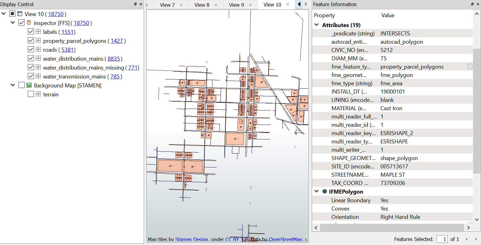
- Check output in DI to see attributes preserved as extended entity data.
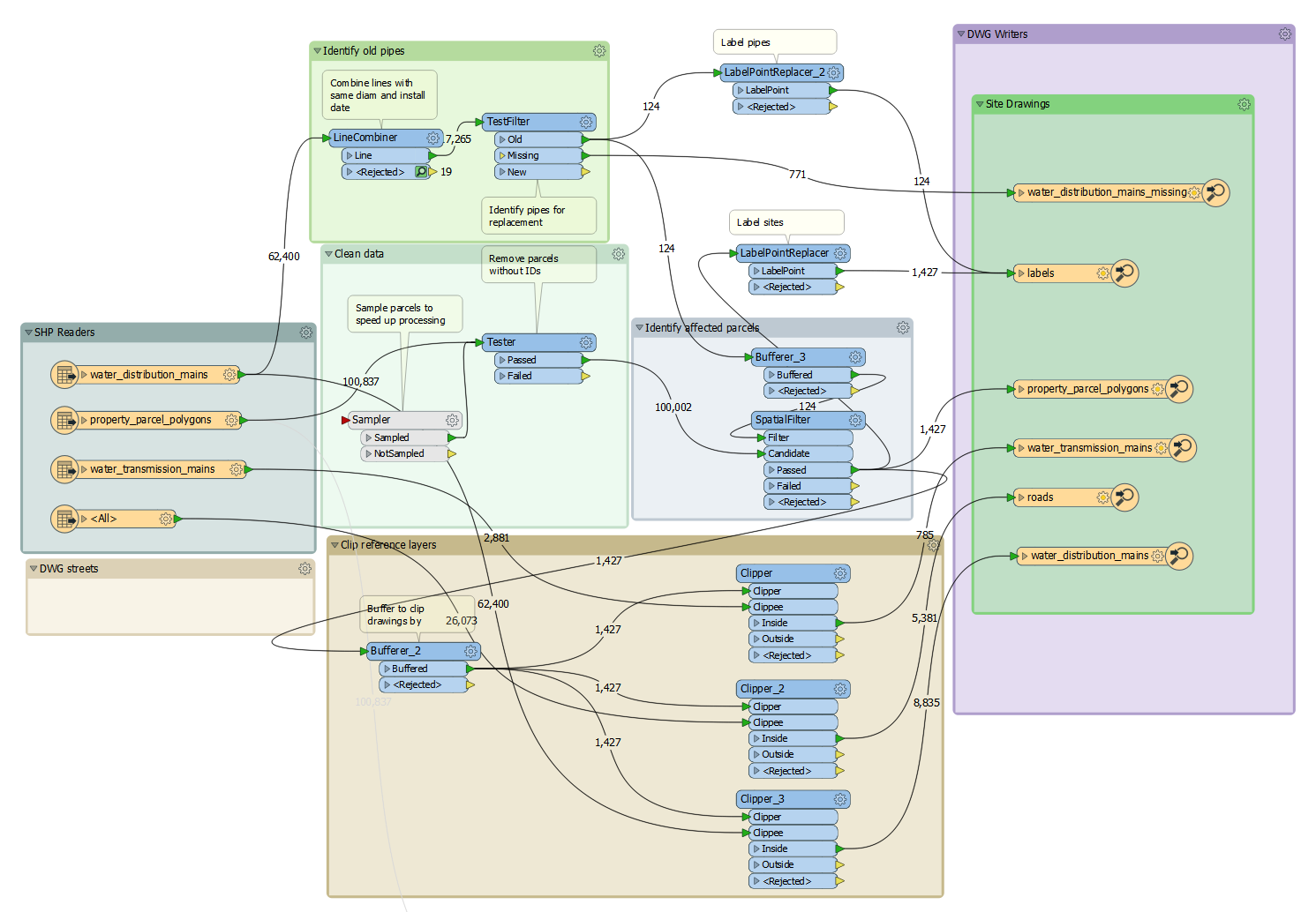
- Identify old pipes: add LineCombiner, TestFilter for Old and Missing (log).
- Clean your parcel data: use a Tester to remove parcels without IDs.
- Identify affected parcels: Bufferer on pipes, SpatialFilter on pipes and parcels, write out parcels.
- Clip reference layers (water and streets): Bufferer on affected parcels, Clipper, write out.
- Add a LabelPointReplacer to create labels for pipes and parcels.
- Add an Excel writer. Use template.
- Intersect affected parcels and pipe buffers, merging attributes. Connect Parcel output to Excel writer.
- Advanced: add an AutoCAD layout: use template layout file, add to DWG fanout.
- Add CAD->GIS data steps here
In-progress example
 CAD Site drawings in Data Inspector
 In-progress workspace
Notes
Want site drawings to have streets, all water mains, water mains to replace, maybe electrical grid. Style site drawings (dwgstyler likely, since multiple layers on feature type. Or do I do I writer with multiple ft layers...) Add layout to site drawings Have parcels and labels, but nothing outside that Note: to read xdata in AutoCAD 2018, go to Express Tools, List Xdata, click your feature, hit enter.